This is the second post in a series that covers a project where the aim is to create a home irrigation system using a Raspberry Pi that waters the plants in the garden based on the weather.
This post outlines the hardware portion of connecting the Pi to the Solenoid and changing state via the terminal.
The project divides nicely into different sections:
- Part 1 - Overview
- Part 2 - Hardware (this post)
- Part 3 - Application
Components:
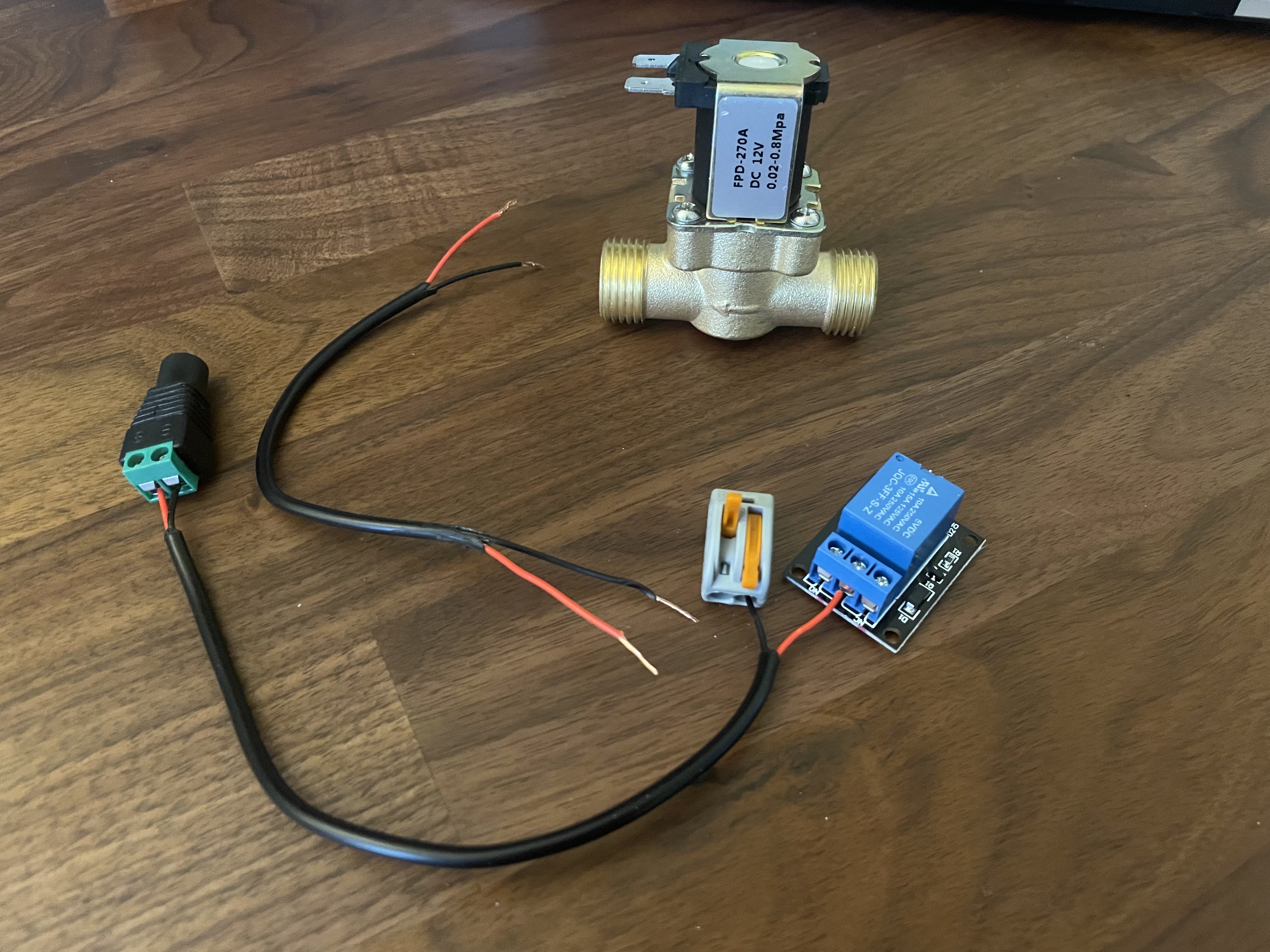
After a bit of research I found that I could put something together using the following components:
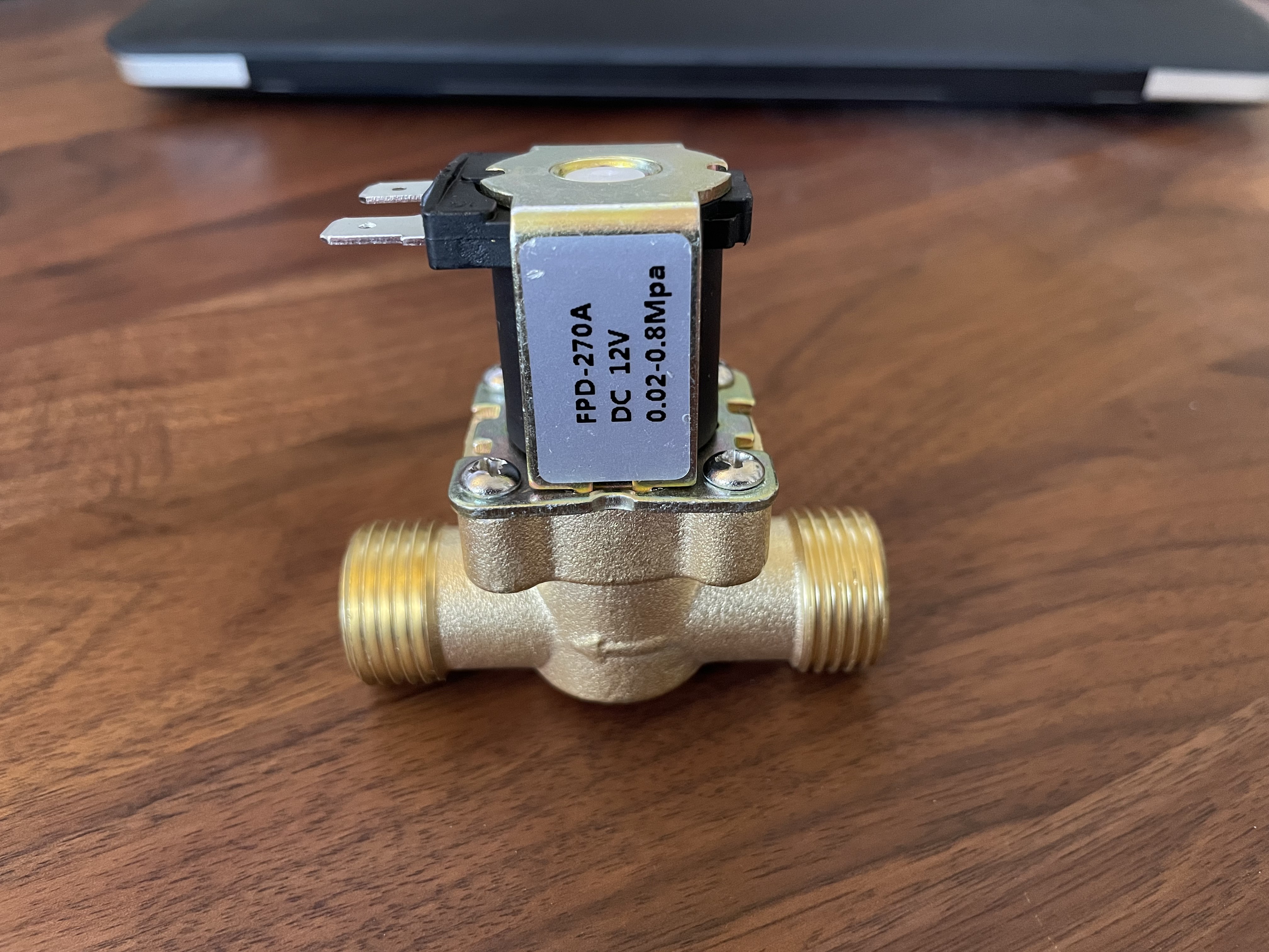
- Solenoid Valve (Normally Closed)
This device can allow or block water passing through depending on whether the unit is receiving power. By using the Normally Closed (NC) variation, it meant that the default non-powered state would not let water through. This was ideal in case anything went wrong (such as a power cut) as I wouldn't end up flooding everything.
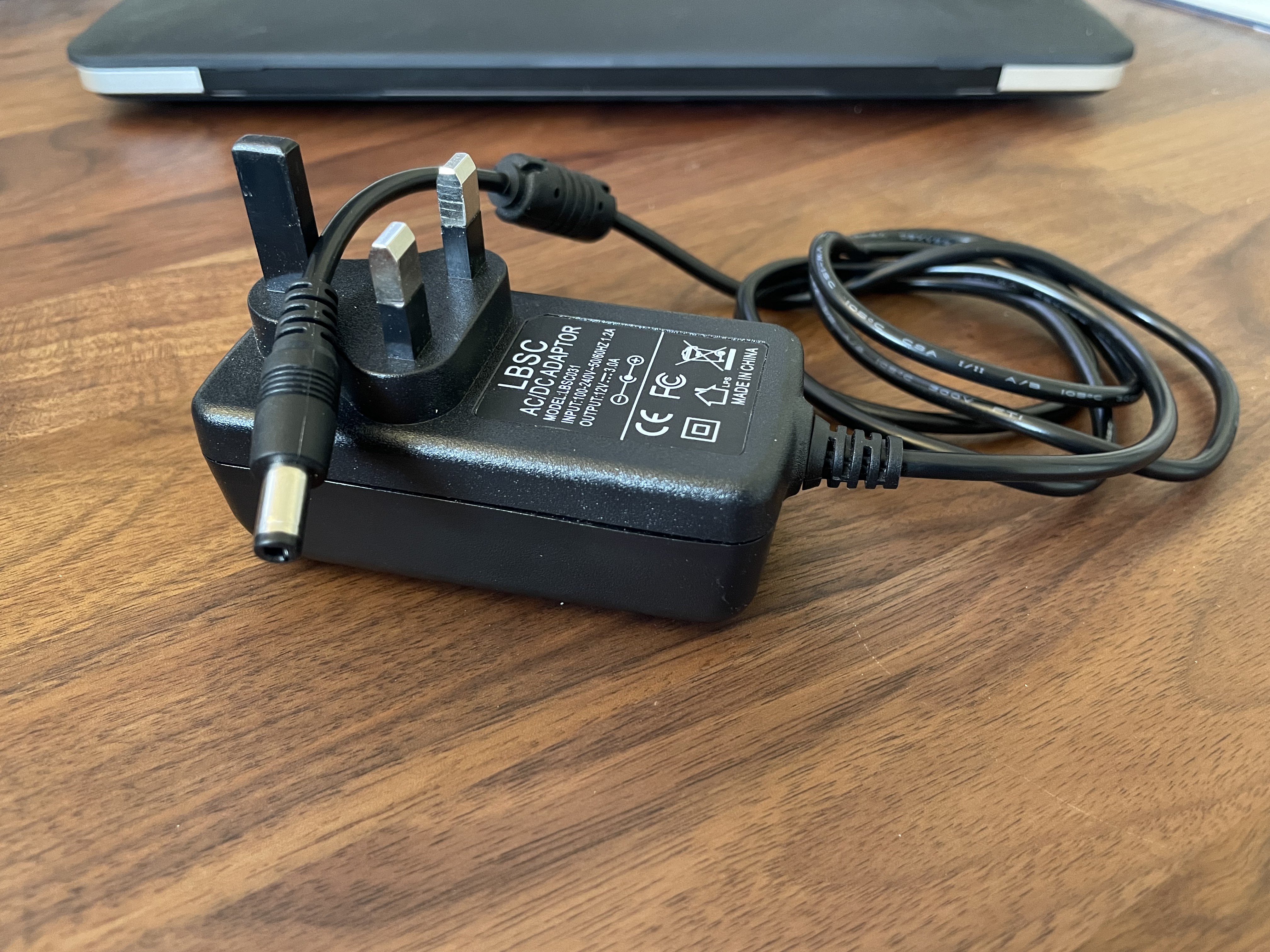
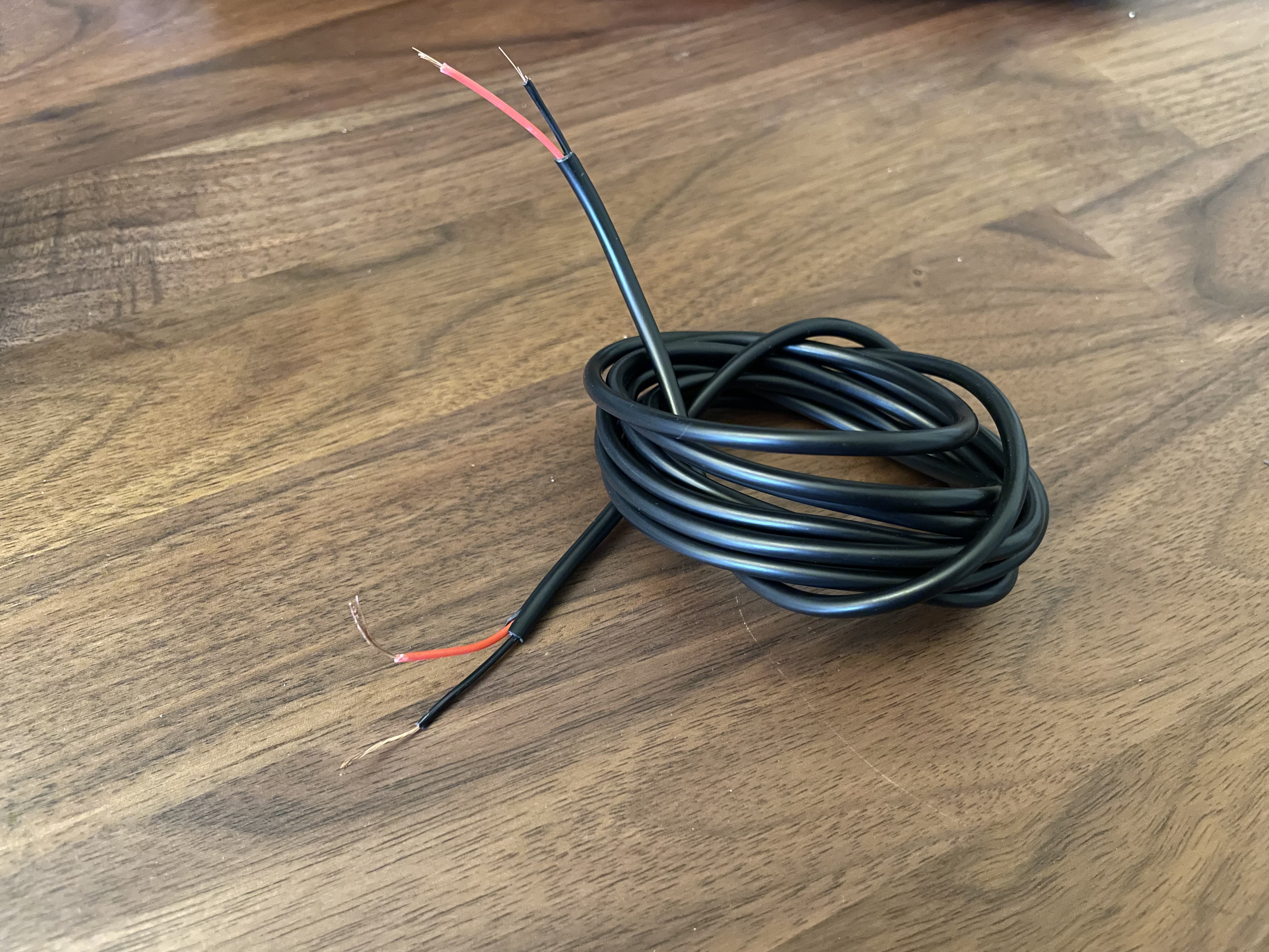
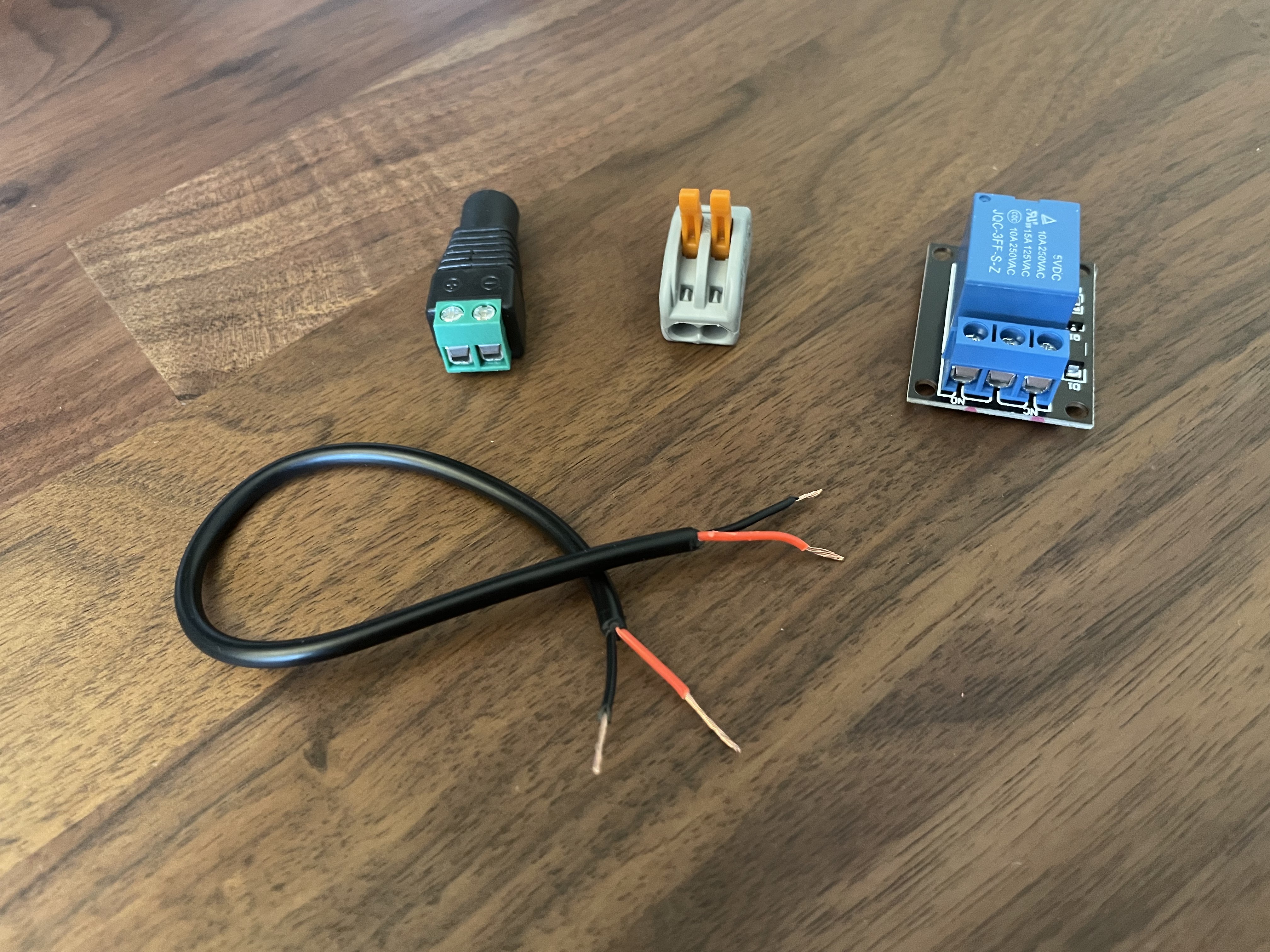
- DC Power and Cable
In order to power the valve, it needed 12V DC. The additional extension cabling was required to connect components and eventually provide enough length for the final installation between power, Pi and valve.
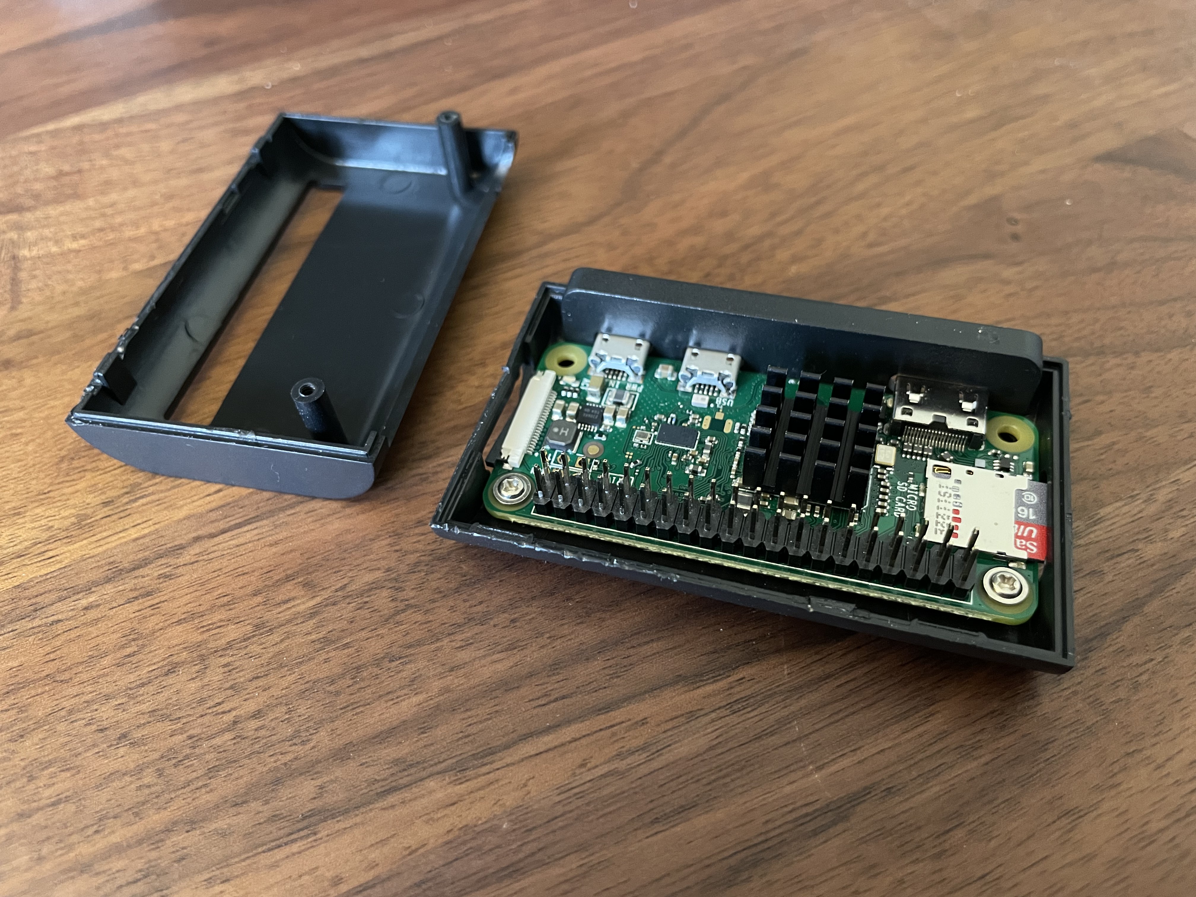
- A Raspberry Pi Zero W (+ power supply)
The Pi will run an API that connects to the boards GPIO pins. This will interact with the Solenoid to supply power when necessary and therefore manage watering. I was looking to keep this hardware in a cupboard so the smaller the Pi the better and supporting WiFi also helped here.
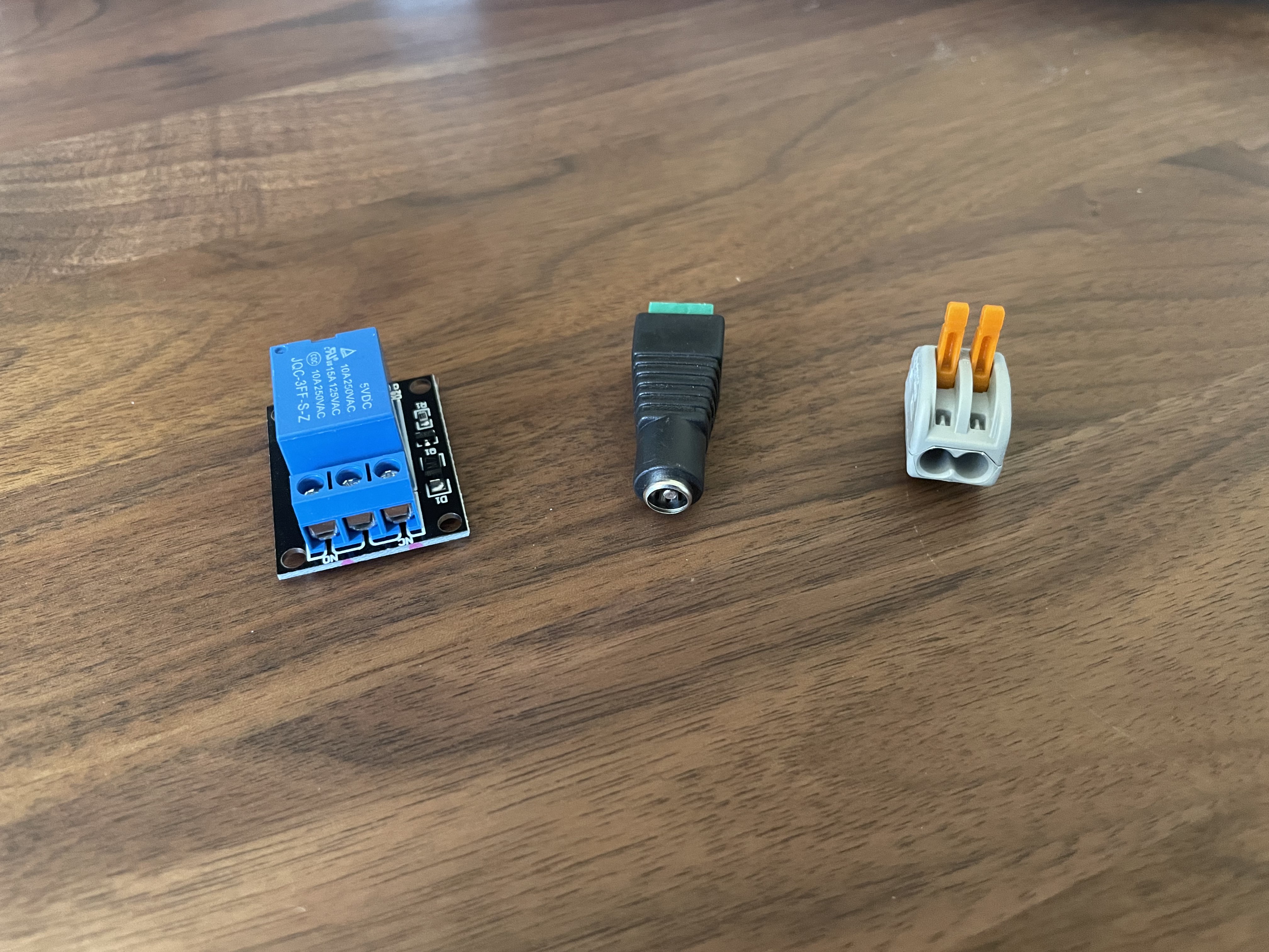
- Relay, DC Adapter, Connector Block, GPIO Cables
The relay module acts as a switch within the circuit between power and the solenoid. The pins at the back allow the pi to connect to the relay using the GPIO cables.
The DC power adapter was used so I could keep the original power plug intact. The connector block allowed for quickly connecting the stripped cabling later on in the process.
Assembly:
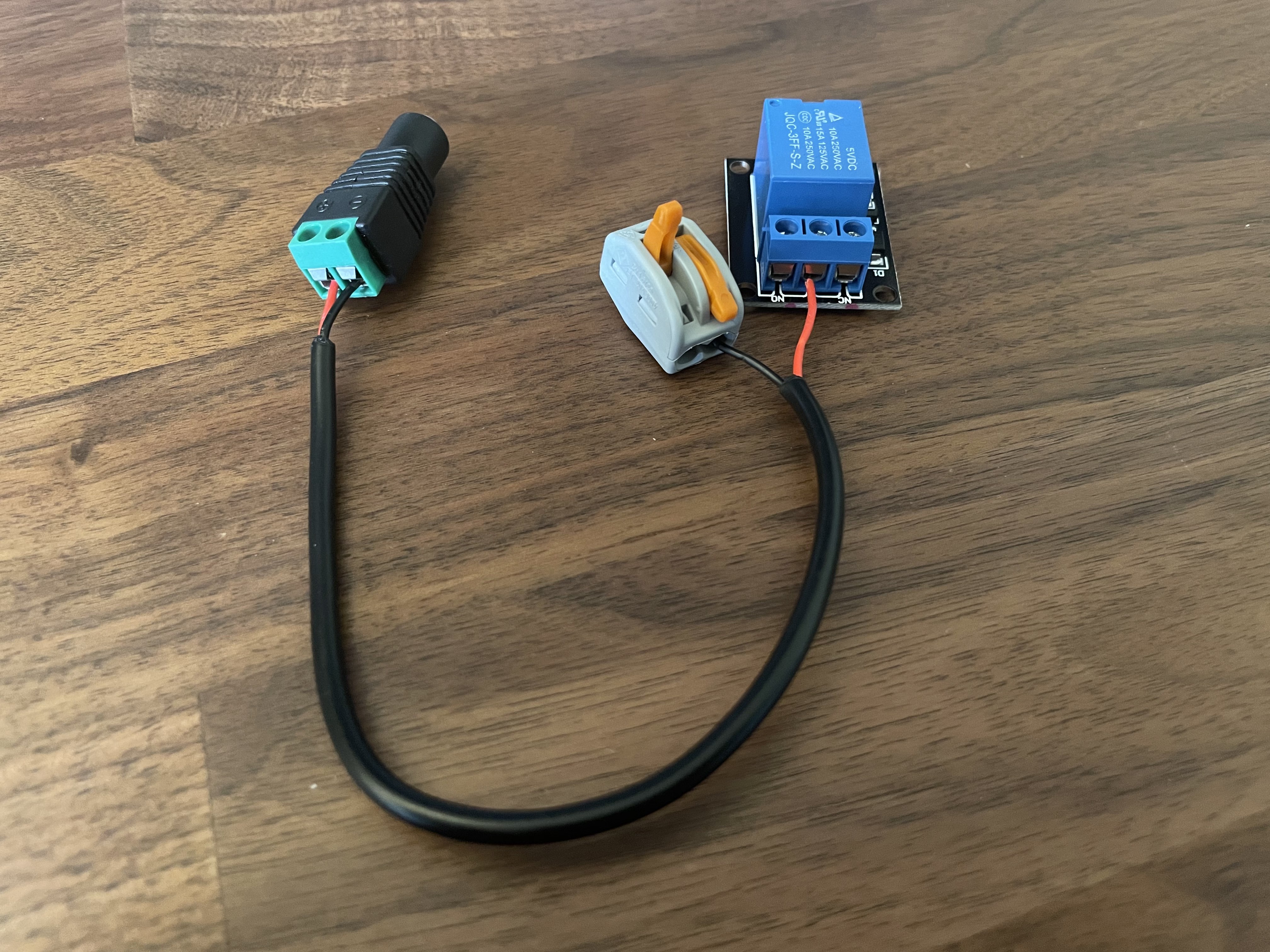
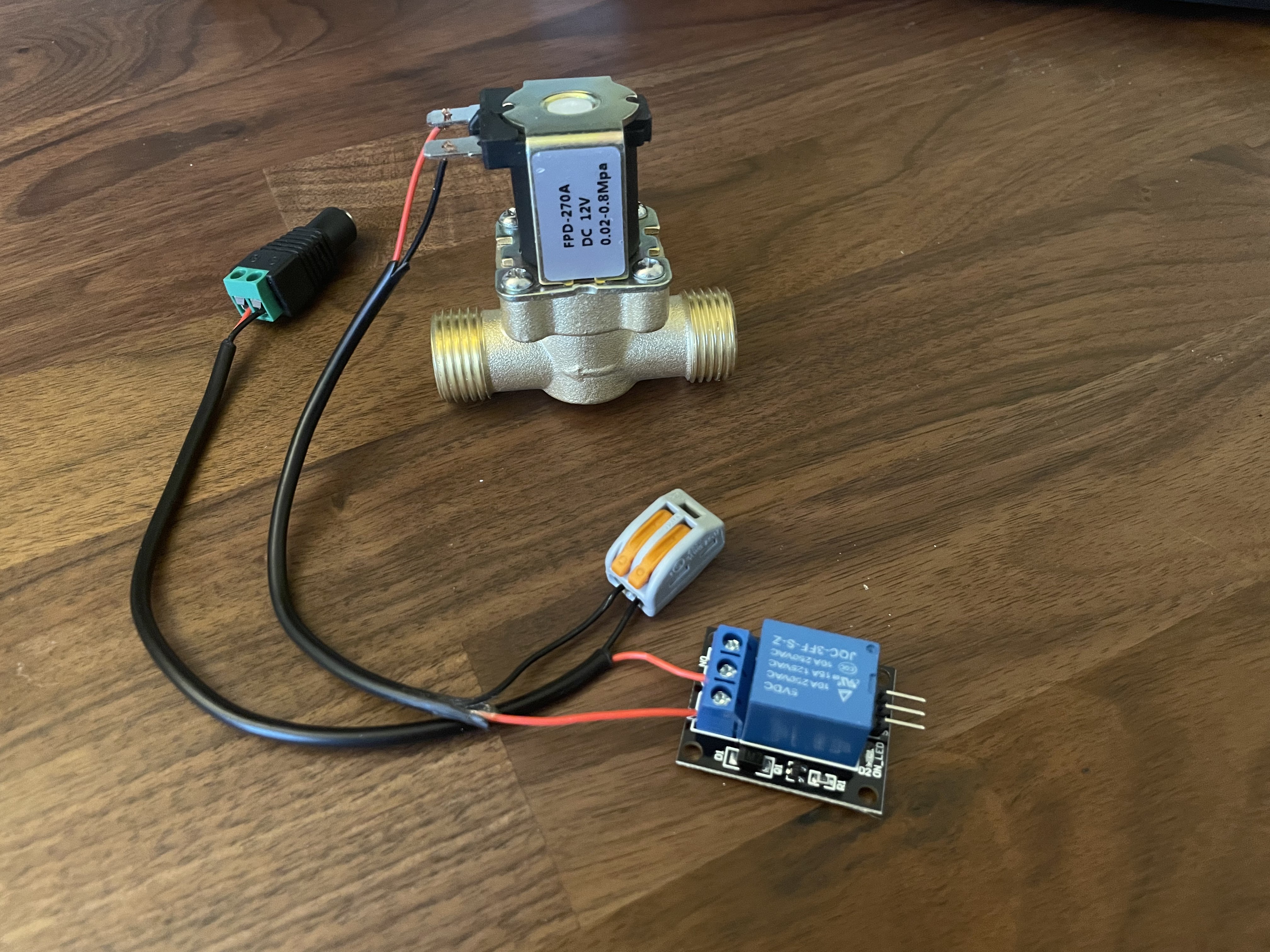
1. Connect DC to Relay
Cut a short length of the DC cable, then split and twist the ends.
Connect one end of the cable to the DC adapter (positive/negative accordingly).
Connect the other end to the middle Relay fixture (positive) and the connector block (negative).
2. Connect Solenoid
Grab the solenoid valve and cut another short length of DC cable.
Connect one end of the new cable to the solenoid valve (polarity doesn't matter).
Connect the other end to the Relay NC fixture (positive) and the free connector block slot (negative).
3. Connect Pi
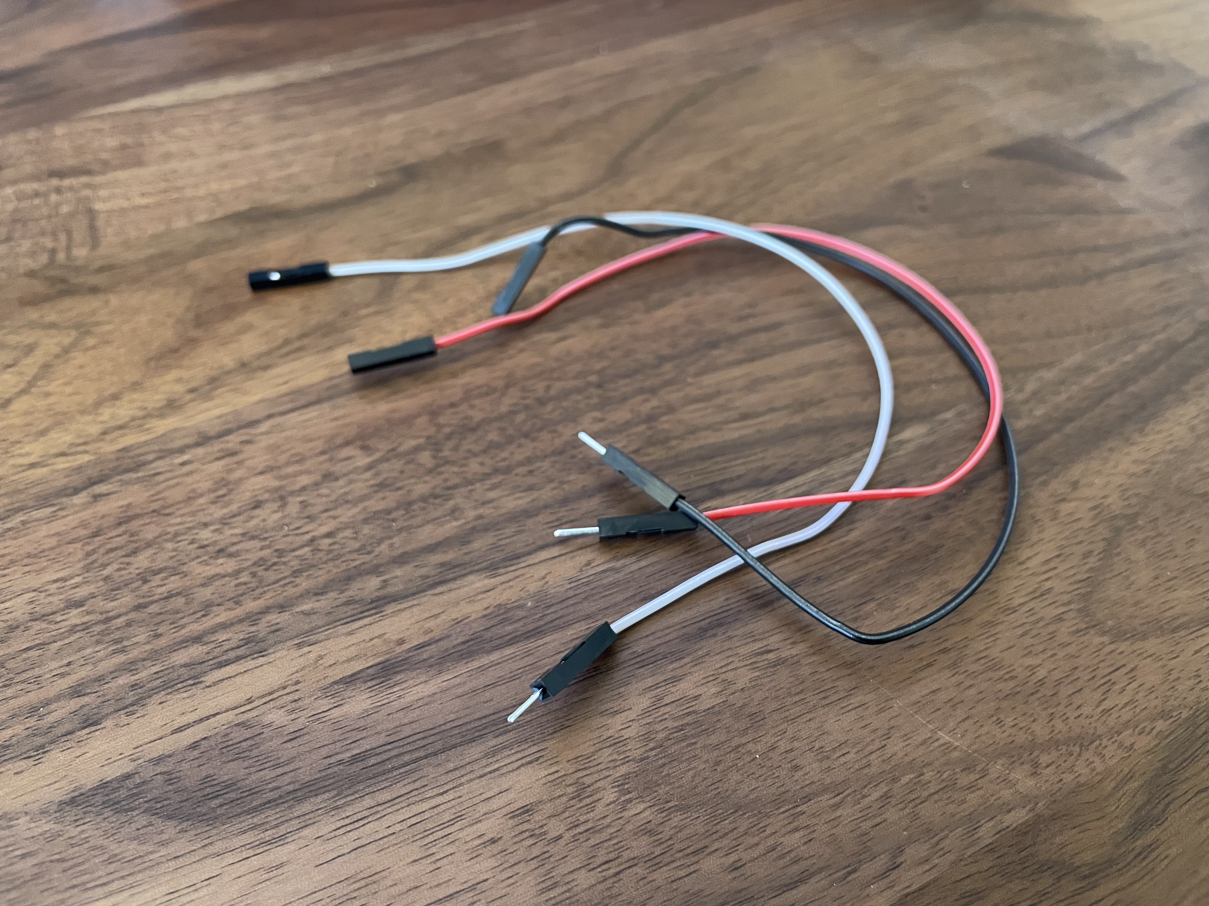
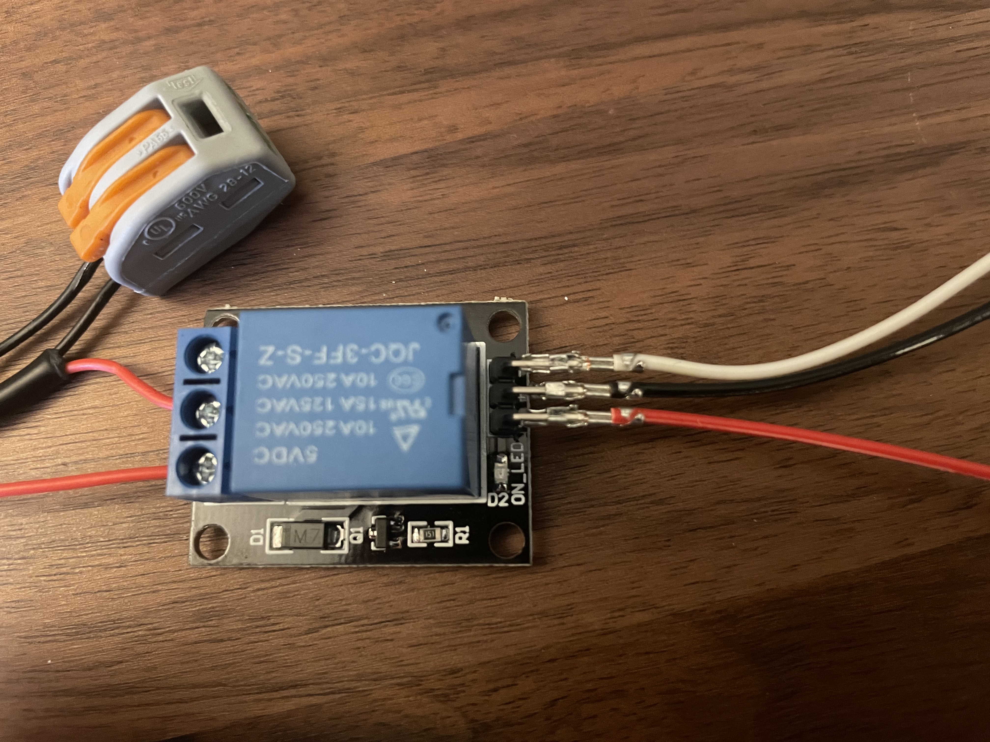
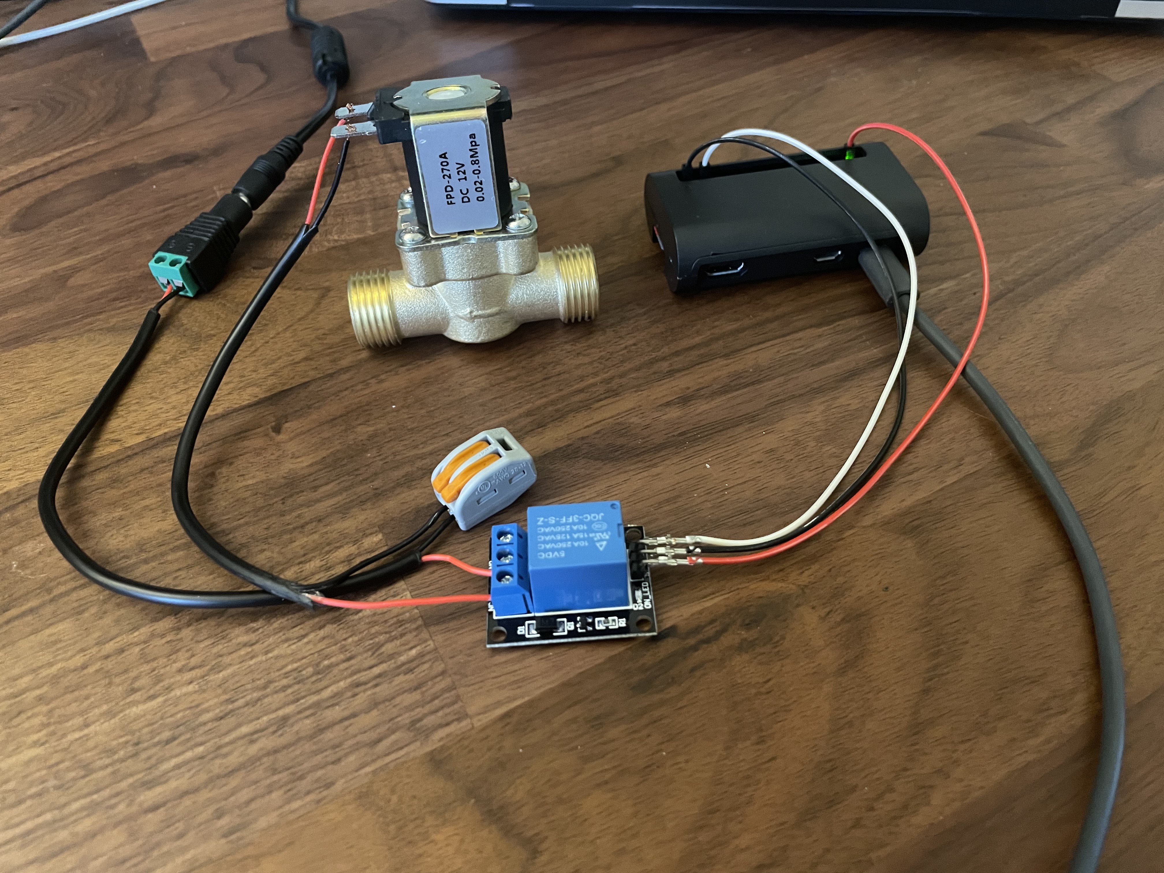
Connect the three GPIO cables to the Relay pins.
From top to bottom in the first image below, the connections are:
- / negative (White)
+ / positive (Black)
S / signal (Red)
(I acknowledge the missed opportunity for consistent colour coordination)
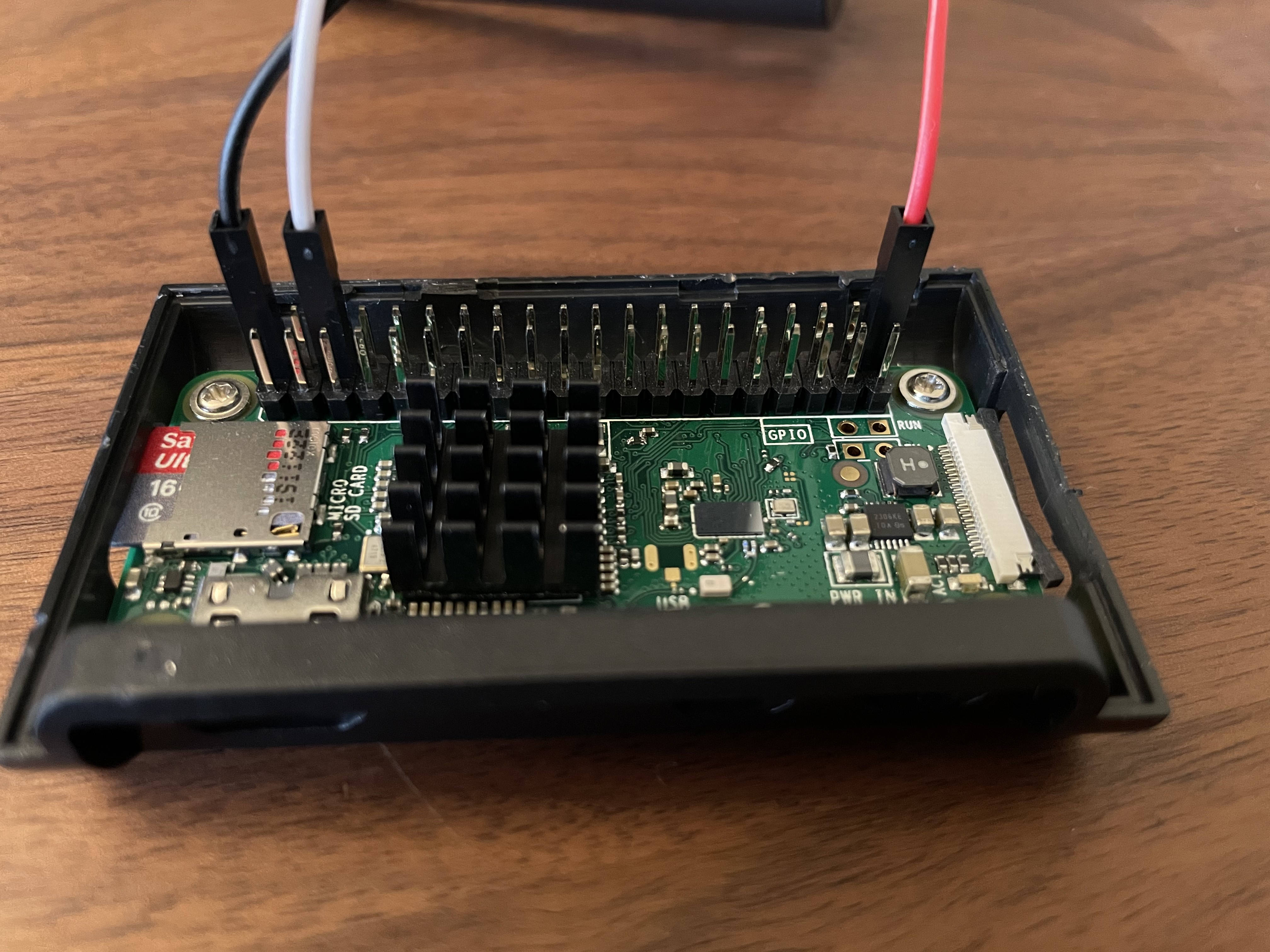
Connect the GPIO cables to the Pi using the following pins:
2 / 5v Power (Black)
6 / Ground (White)
40 / GPIO 21 (Red)
4. Power Up & Demo
Use the DC and Pi power cables to start everything up.
The Pi has already been setup on the network so the next step is to connect and test.
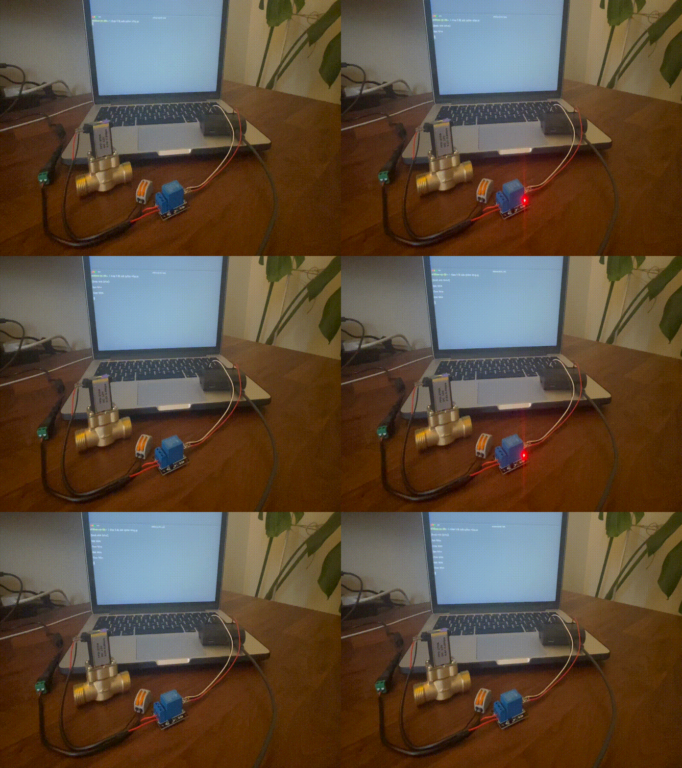
This script can serve for a quick test to make sure you can see and hear the valve and relay react to the change in power.
import RPi.GPIO as GPIO
import time

GPIO.setmode(GPIO.BCM)

second_wait = 3
relay_module_pin = 21

GPIO.setup(relay_module_pin, GPIO.OUT)
GPIO.output(relay_module_pin, False)

try:
    while True:

        print("Open")
        print(" ")

        GPIO.output(relay_module_pin, True)
        time.sleep(second_wait)

        print("Close")
        print(" ")

        GPIO.output(relay_module_pin, False)
        time.sleep(second_wait)

except KeyboardInterrupt:

    GPIO.cleanup()
The code above in action below:
5. Box Up:
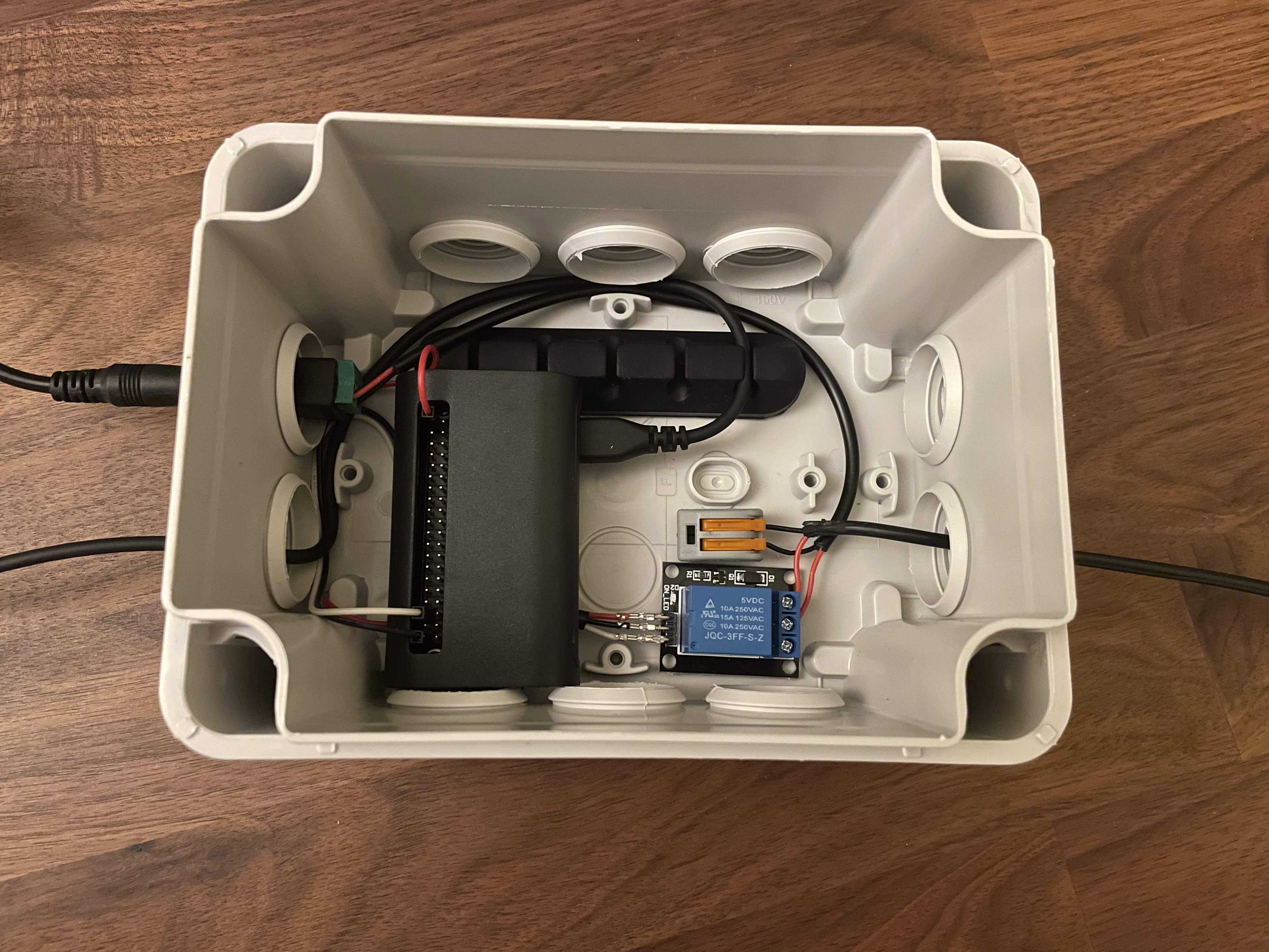
After everything was tested, a spare outdoor junction box was used to house the components to keep things tidy. The DC cables were replaced with longer lengths to reach the garden and power source. The USB and DC power enter on the left, then the cable to the Solenoid exits right.
The next and final part goes over a few sections that make up the application such as weather checking, job scheduling, notifications and how to prevent duplicate jobs: Part 3 - Application.
